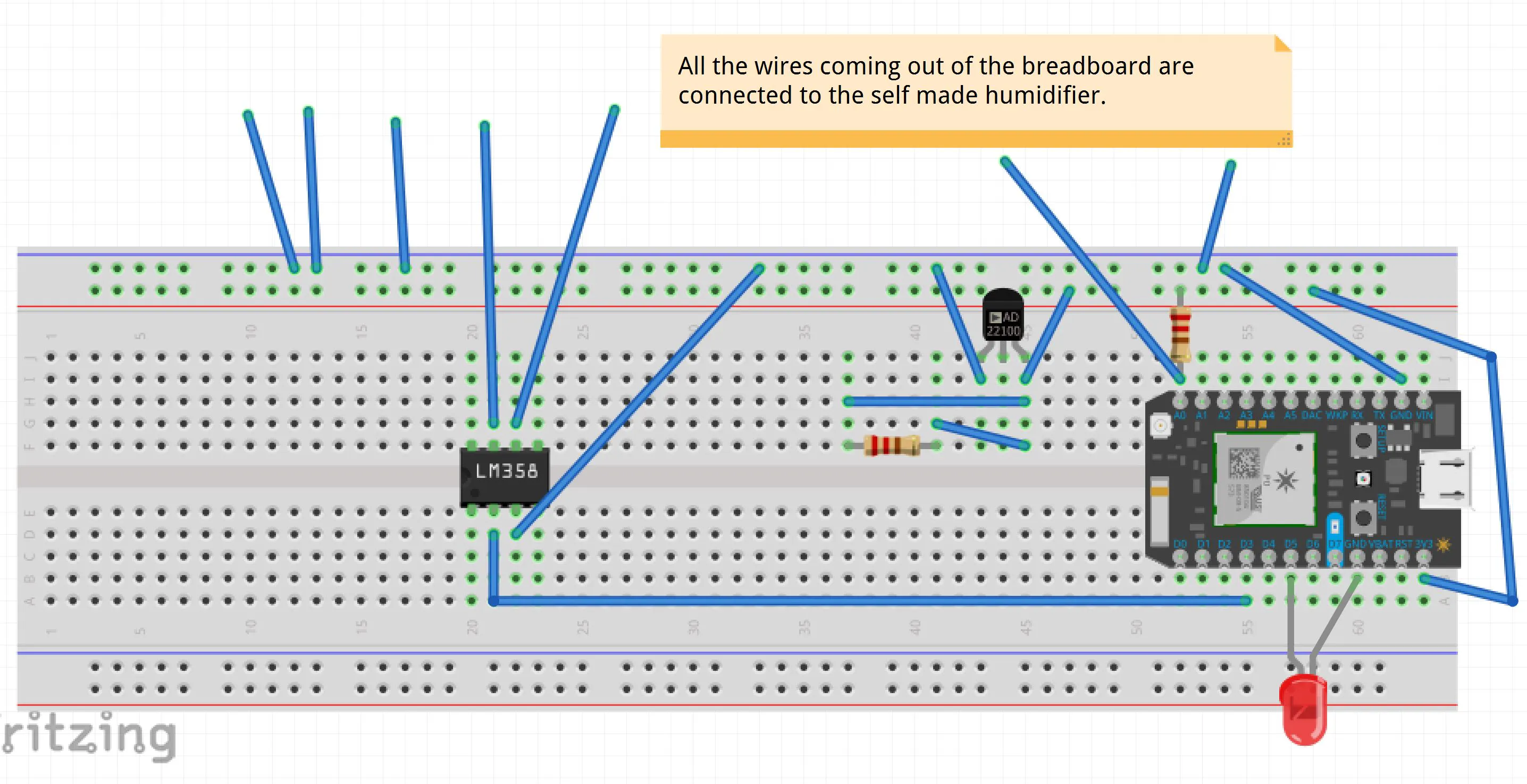
Digitizing circuit diagram for the humidity sensor data Humidity Sensor: Humidity is the amount of water vapor present in the air. It can be a reliant indication of the likelihood of precipitation. The circuit is very straight forward, as you can see in the picture above. The red wire is supplying the sensor with 3.3 Volts from the Arduino board. The black wire is ground i.e. 0 Volts.

In this project, i wanted a startup animation screen which would display the my Channel name and Project name, next I needed to display the data from DHT11 sensor, so i set the cursor position on my LCD according the convenience and simply dumped the Temperature and Humidity values from the Variables that hold the data from sensor on the LCD screen using lcd.print command and that's pretty
Humidity Sensor + Arduino : 5 Steps (with Pictures) Circuit Diagram
The DTH11 is a sensor designed to sense the moisture level present in any matter.hobbyist use to implement them into the prototype and make a prototype of it.Usually, the DTH11 consists of four pins out which three are used for the implementation. The pins are accordingly ordered as . VCC pin; Data-out pin; GND pin

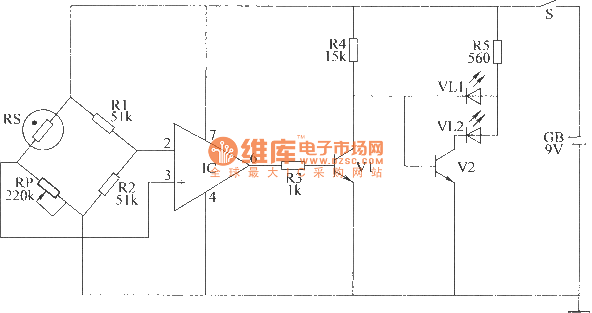
Learn How to Make DIY Weather Station With Arduino and DHT11 Sensor in a Detailed guide along with Arduino Code and Circuit Diagram. Monday, March 17 2025 Breaking News. Colour Sorting Machine Project Arduino and TCS3200 The Arduino Weather Station uses the DHT11 sensor to read the surrounding temperatures and humidity. This sensor is The humidity sensor DHT22 is an affordable and easy to use sensor. To use this sensor with arduino boards you need to have DHT library file, you can get here. Circuit diagram . To wire up this sensor with arduino follow these steps, first connect bias to sensor that is +Vcc 5 volt to pin 1 and Ground GND to pin4. Then put external resistor 10K Working of Humidity sensor Circuit: In this circuit we are using an Integrated Humidity Sensor HIH-4030, three Op-Amps to sense the output from the sensor and switches the indicator LED's based on its intensity. For showing the results we have 3 LED's. The sensor is very simple and has 3 pins.
Humidity Sensor : 4 Steps (with Pictures) Circuit Diagram
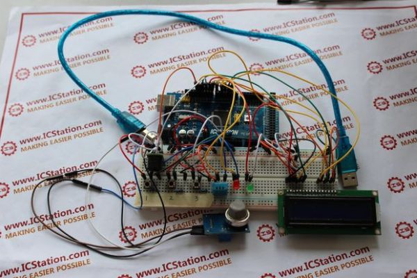
In our previous article, I have explained how to interface temperature humidity sensor with arduino and read out displayed on serial monitor of arduino IDE. In this post I have explained how to display the reading on a 16x2 LCD display for the proposed digital temperature/humidity meter using Arduino.
The simple programmable humidity sensor circuit I have explained in this article can be used for controlling or maintaining a suitable level of humidity inside a close premise. The circuit could be used in poultry farms or similar areas where humidity level becomes crucial for keeping the animals healthy. The idea was requested by Mr. Tanvir
