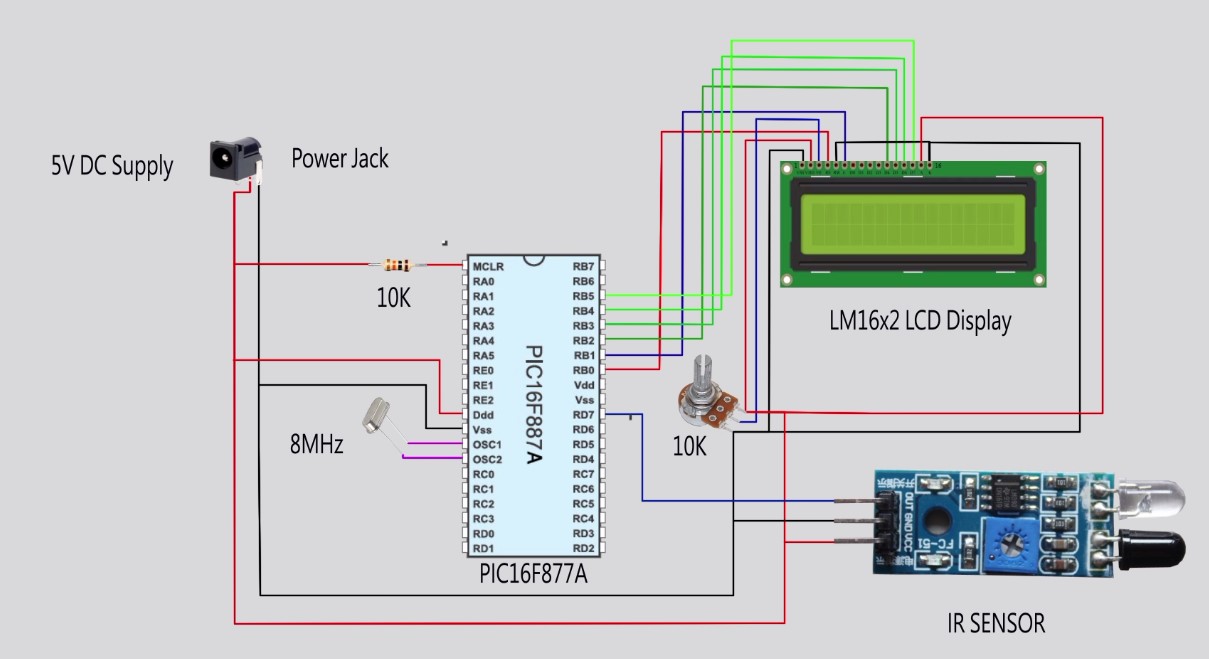
IR Sensor interfacing with microcontroller Mikro C Circuit Diagram The microcontroller communicates with the sensors and actuators to acquire data or trigger actions based on the input received. The interfacing process involves the following steps: Identify the Sensor or Actuator: Determine the type and specifications of the sensor or actuator you want to interface with. Common examples include temperature
Typically, the bandwidth for temperature sensors is much lower than 50 or 60 Hz so a simple low-pass filter will work well in many cases. Other measures to keep noise away: • Keep the sensor wires short. • Use shielded sensor cables with twisted pair wires. • Use a dedicated precision voltage reference, not the microcontroller supply.

Using Analog Sensors with Microcontrollers: A Beginner's Guide Circuit Diagram
In simple terms, sensor interfacing is the process of connecting sensors to microcontrollers or other processing systems. This allows microcontrollers to acquire, process, and respond to sensor data, facilitating real-time environmental interaction. This interface enables microcontrollers to: Acquire the signals from sensors
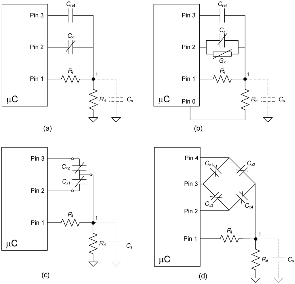
The microcontroller's input has a high impedance so the changes in the current drawn by the sensor are converted into a measurable voltage by the 250ohm resistor. The value of the 250 ohm resistor is determined using the sensors maximum current 20mA and the micro-controllers maximum input voltage which if Vcc at 5v for the Arduino.

Sensor Interfacing 101: A Comprehensive Guide Circuit Diagram
This article discusses the "ins and outs" of interfacing analog sensors to a microcontroller's analog-to-digital converter (ADC) input pins 1.As shown later in Table 1, a great number of sensors produce a voltage output that varies in response to a change in a physical parameter such as temperature, pressure, or magnetic field intensity.. Voltage output sensors with low output impedance
